Friday, April 8, 2016
A Working Leach treadle Wheel!
I set up the wheel temporarily to make sure it worked correctly and smoothly prior to breaking it down for finishing. All I can say is success!
It needed some minor adjustments, but works exactly as I had hoped. Here I cranked it up, jumped off and filmed a short video of the wheel in action.
Leach Treadle Wheel Update
I have done a number of things on the Treadle Wheel since the last post.
 Pacifica used to be the only electric wheel using a 1" shaft, but I discovered that Brent has been making some of their new models using a 1" shaft rather than the 3/4" shaft they have used for years. This makes both their 12" & 14" wheel heads available with the 1" shaft, which is perfect for the Leach Treadle Wheel! I opted for the 12" wheel head, as this is the typical size used on a treadle wheel (as specified by Bernard Leach) and it gives much more room around the wheel head than a 14" would. I also located some 1/2" Dupont Corian remnants to fabricate a splash pan. They where typically made from wood and lined with copper or zinc. I have to believe that had Bernard had access to Corian he would have chosen it too, as it is water proof, highly durable, and will last forever. The hole for the shaft has a piece of PVC pipe glue welded into place. The outside of the splash pan will have a 1/4" veneer of maple to add to the wheel's looks.
 Here I have the wheel mostly mocked up to see if everything is working correctly...and it does! The flywheel is made from four layers of 3/4" birch plywood and has a 1/2" layer or Corian on top. In this picture the flywheel is installed up side down.
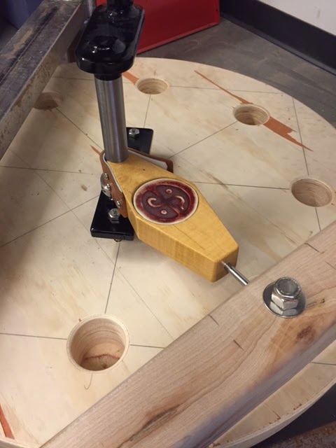
 As an homage to Leach, I created a porcelain disk and inset it into the treadle/shaft connector. It bears the insignia of the St Ives Leach Pottery.


Koren Hybrid Wheel Update
So I started building a Korean Hybrid style wheel that I drew up some plans for...
I purchased remnant metal from the metal yard to fabricate the base and main rod from which the wheel is supported. I cut the pieces yesterday and welded them up today making sure that they are FLAT, SQUARE, and that the vertical rod is PLUMB. The finished base is 28" square and the rod is 35" tall from the ground, which I am going to cut to accommodate the perfect height.

At the top of the rod I have a 1" section which I have drilled a 90 degree countersink into creating a perfect "V." This piece is separate for two reasons, the first is that it is much easier to drill a 1" section of rod on the drill press than a 36" section of rod, secondly and most importantly...I am going to harden this section of steel so that it does not wear out as easily as stock mild steel would. Once hardened, this section will be welded back on top.
 Here is the "live center" with the morse shaft cut off, which will be inserted into the wheel head and will mate up with the counter sunk cup.
 This is how the mate up! they only make contact at the very tip, which creates very little friction = easier to turn and keep momentum!
 More to come!
I purchased remnant metal from the metal yard to fabricate the base and main rod from which the wheel is supported. I cut the pieces yesterday and welded them up today making sure that they are FLAT, SQUARE, and that the vertical rod is PLUMB. The finished base is 28" square and the rod is 35" tall from the ground, which I am going to cut to accommodate the perfect height.

At the top of the rod I have a 1" section which I have drilled a 90 degree countersink into creating a perfect "V." This piece is separate for two reasons, the first is that it is much easier to drill a 1" section of rod on the drill press than a 36" section of rod, secondly and most importantly...I am going to harden this section of steel so that it does not wear out as easily as stock mild steel would. Once hardened, this section will be welded back on top.


Subscribe to:
Comments (Atom)